
Application notes on a fanless solution: UHP-1000
By: Mathis Picot /Technical Service Center
mathis@meanwell.eu
MEAN WELL’s UHP-1000 series has been designed to provide a fanless solution. The unique fanless design solves dust ingression issues, thus effectively reducing equipment maintenance frequency, cost overhead, while at the same time making UHP-1000 perfectly suitable for indoor equipment with silent operation requirements. Its comprehensive functionalities are widely used in various applications, some of which are detailed in depth, below, as application examples.
UHP-1000’s adaptive control and flexible heat dissipation options makes it a suitable solution for a wide range of applications, from industrial constant voltage applications to charging systems. The semi-potted design makes UHP-1000 a strong and slim fanless power supply resilient to vibrations and dust ingression along with considerably extended lifetime. It comprises international certifications for IEC/EN/UL 62368-1, and compliance with both EN61558-1 and household safety EN60335-1 are available upon request. It is also capable of a high-altitude operation of 5000m under a wide working temperature range from -30oC to +70oC and with universal AC mains input. The inclusive output voltage range of 12V, 24V, 36V and 48V of UHP-1000 makes it adaptable to various systems.
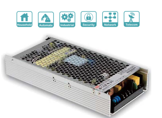
Fig 1: UHP-1000
Programmable output:
Along with DC OK signal, Remote ON-OFF control, and an auxiliary 12V output, UHP-1000 also comprises Programmable Voltage (PV) and Programmable Current (PC) functions, thus allowing a wide output voltage range, with fixed or dynamic control to fit most applications. For example, a thermal controlled chamber might sense the temperature and adjust the power supply output voltage to control the heating element accordingly. Programmable Current can be useful for charging applications or LED control.
As shown in Figure 2 below, UHP-1000 output voltage can be adjusted with an external DC 2.5V to 6V signal, allowing an extra adjustment from 50% to 120% of the rated output voltage. When using PV control, the maximum output current is automatically adapted taking into consideration the set output voltage to prevent overpower or overheat.
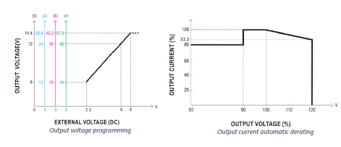
Fig 2: PV control and automatic derating curve
PC mode can limit the current down to 20% of the rated output current (Figure 3). Many applications such as motors or capacitive loads create high inrush currents. PC control is particularly useful to limit this inrush current to a certain constant current value determined by the user. Programmable current control is also suitable for other applications that require a constant current operation, such as LED lighting for brightness adjustment or charging systems.
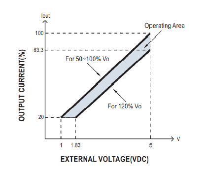
Fig 3: Output current programming
A combination of both PV and PC controls is possible which makes UHP-1000 very flexible and suitable for charging applications (cf. Application Example 1) as well as for applications with high inrush currents (cf. Application Example 2).
Vibration and shocks:
The semi-potted structure associated with the aluminium case of UHP-1000 result in a strong and reliable mechanical design capable of withstanding 5G vibrations that meet the high demand in terms of resilience to shocks and vibrations in the automotive industry.
Thermal considerations and design guide:
The aluminium enclosure itself has been specially conceived to efficiently dissipate the generated heat while getting over the need for using integrated fans. This considerably increases the lifetime and the reliability of UHP-1000, while making it suitable for audible noise-sensitive applications, and dust prone environments. The optimized thermal management makes it possible to achieve a low-profile design of 41mm along with a high power density. Its slim form factor enables its use for applications with limited available space.
In order to take full advantage of the potential of UHP-1000, special attention should be brought to the cooling method. Many options are available, making UHP-1000 seamlessly integrable into already existent systems:
1. Convection cooling:
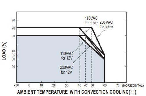
Fig 4: Convection cooling derating curve
Convection cooling is the most convenient way to dissipate the heat generated during power supply operation. It requires no fan, thus there is no emission of audible noise and no forced dust ingression inside the power supply. This solution is viable for loads drawing below 60-70% of the rated power. To allow natural airflow out of the unit, a clearance distance of 10cm above it should be respected. For higher power demand, forced air cooling and conduction cooling are more suitable.
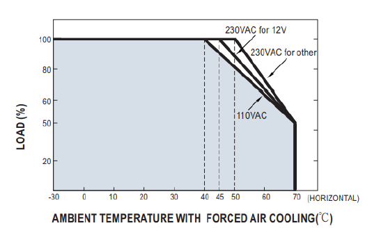
Fig 5: Forced air cooling derating curve
If a need for higher power arises, forced air cooling is an option. Adding an external fan to the side of the UHP-1000 will allow a better heat dissipation. A suggested installation is shown below:
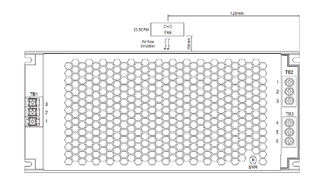
Fig 6: Fan configuration
This solution can take advantage of an already existing fan in your installation, as long as it provides enough airflow to maintain the unit to a temperature comprised within its operation range.
3. Conduction cooling:
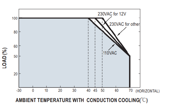
Fig 7: Conduction cooling derating curve
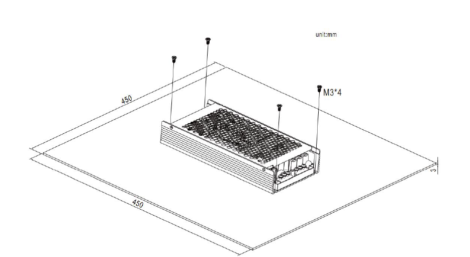
Fig 8: Aluminum plate configuration
No matter what is the selected solution, here is a simple way to verify that the chosen cooling method is adapted:
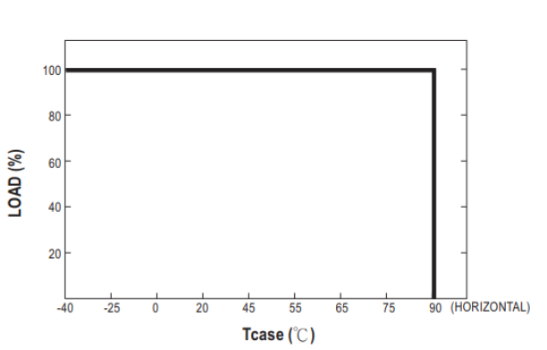
Fig 9: Case temperature derating curve
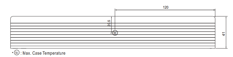
Fig 10: Tc point location
Another important factor to take into account is the ambient temperature. For all cooling methods, if the ambient temperature reaches 40-50oC, the user should limit the power drawn from UHP-1000 according to the derating curves. If necessary, it is recommended to upgrade to higher power products to ensure the reliability of the system.
Application examples:
The versatility of UHP-1000 allows its use for many charging applications: from lead-acid batteries to super-capacitor banks, UHP-1000 can efficiently and reliably adapt to each situation:
Lead-Acid battery:
Below are the ratings of a 12V/200Ah Lead-Acid battery as an example.
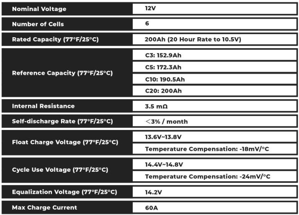
-Constant current operation: According to the battery specifications, the maximum charging current is 60A. Hence, PC control should be set at 60A by applying an external voltage of 4.5V to PC pins.
-Floating operation: The charging voltage should be reduced to 13.6V here. This can be done by tuning down the integrated potentiometer SVR or, by applying an external voltage of 5.6V to PV pins.
Supercapacitor banks:
Regarding super-capacitor banks, attention should be brought to the maximum capacity of the bank. If the capacity of the bank exceeds these values, the power supply will enter Under Voltage Protection mode because of the low voltage imposed at the beginning of the process by the discharged bank, and will shut-down after 3s.
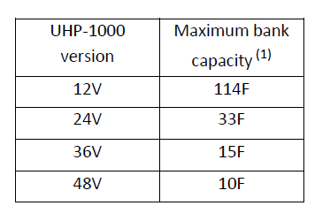
Table 1: Supercapacitor bank maximum capacity
The amount of heat generated by the heating element can be conveniently controlled using PV function. Indeed, the power dissipated by a resistive element is P=V²/R, so the output voltage is directly correlated to the amount of heat produced. This can be particularly useful when the system needs different heating stages, with different temperatures.
Also, most heating elements have the characteristic of presenting an extremely low resistance at start-up which will lead to high inrush current. UHP-1000 automatically clamps the inrush current at 105-120% of the rated output current as long as it lasts less than 3s. Otherwise, the unit will enter Overload Protection mode and will shut down after 3s.